1. simulation of logic gates using VHDL
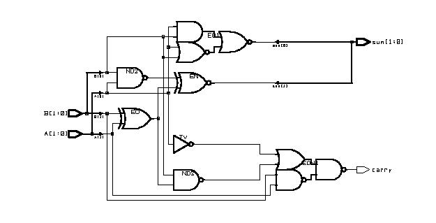
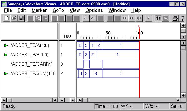
2. simulation of half-adder & full-adder
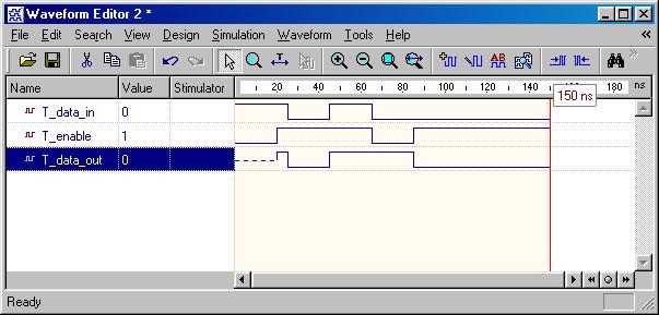
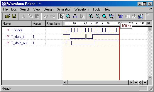
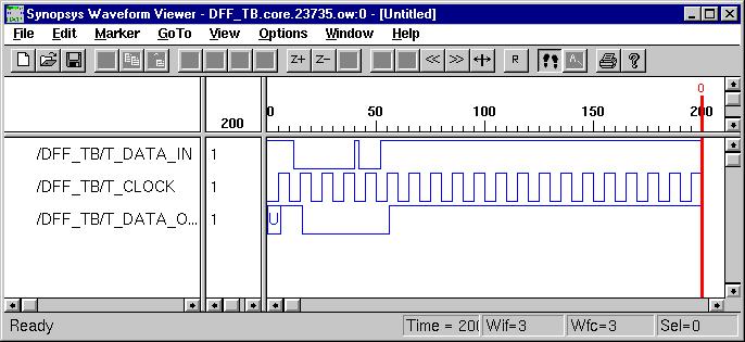
3. simulation of D-flip flop
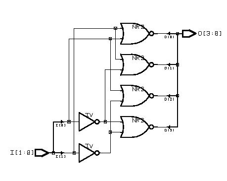
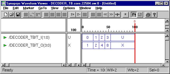
4. simulation of 3-8 decoder
5. simulation of 16:1 multiplexer using 74151
6. simulation of 16:1 multiplexer using 74150
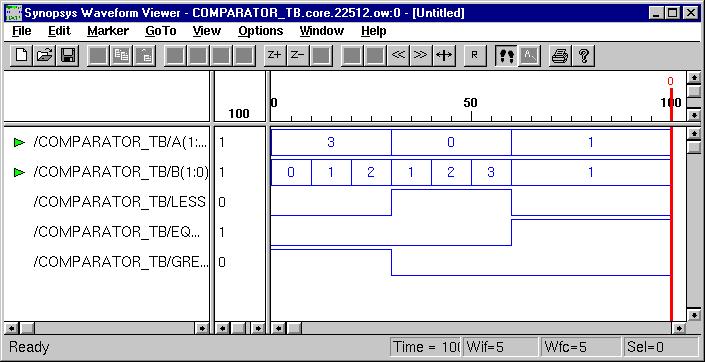
7. simulation of 4 bit comparator
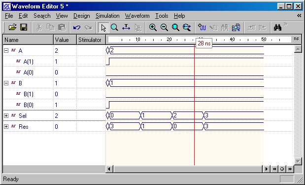
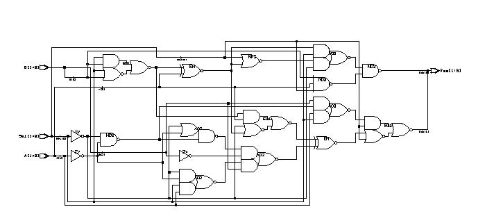
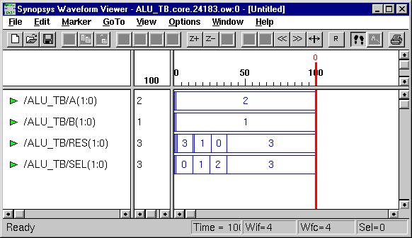
9. simulation of ALU (74381)
10. simulation of decade contact
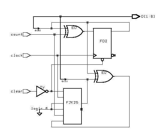
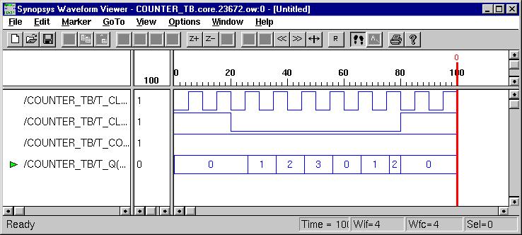
11. simulation of 4 bit counter
12. simulation of 32 bit one's counter
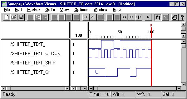
13. simulation of universal shift register
14. simulation of priority & coded
Wednesday, July 30, 2008
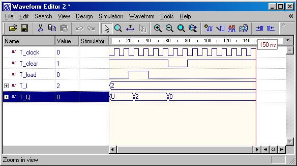
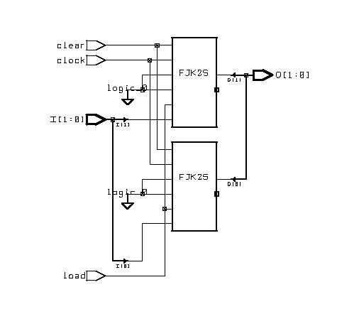
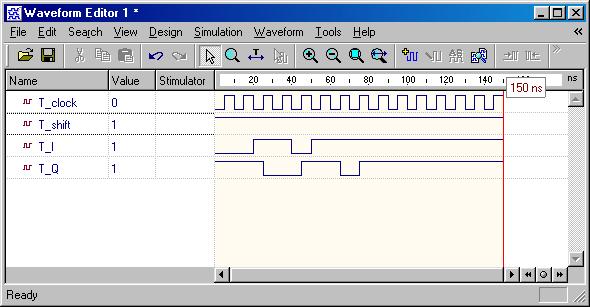
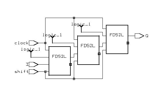
Typical Sequential Components
Typical Sequential Components
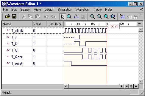
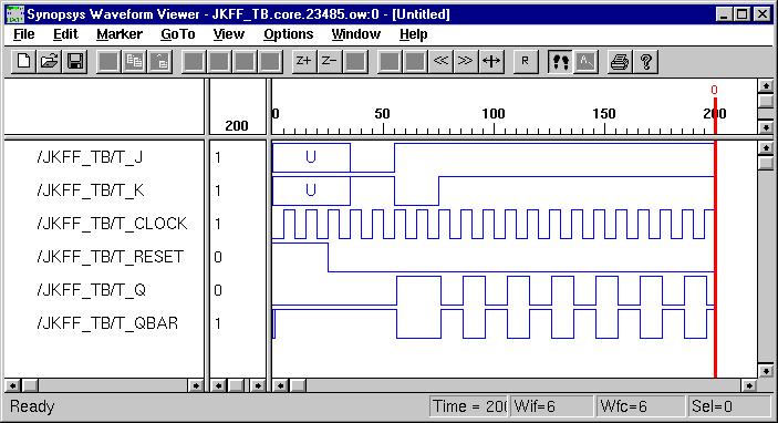
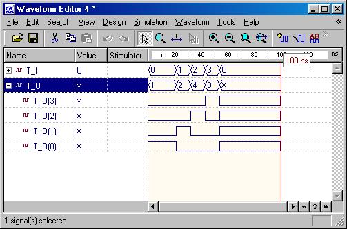
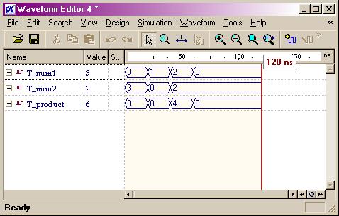
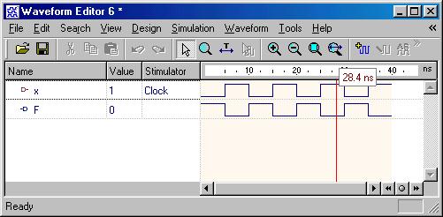
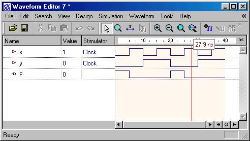
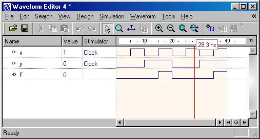
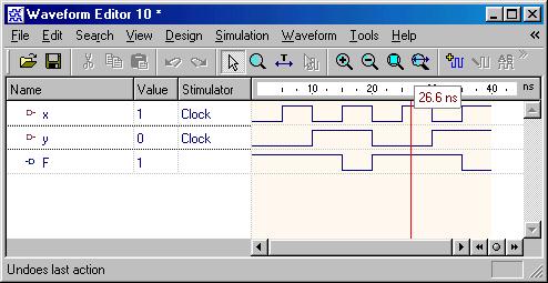
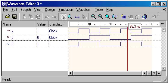
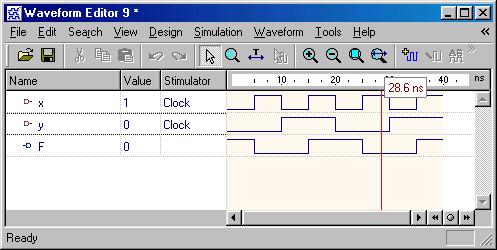
Typical sequential components consist of registers, shifters and counters. The concept of generics is often used to parameterize these components. Parameterized components make it possible to construct standardized libraries of shared models. In the behavioral description, the output transitions are generally set at the clock rising-edge. This is accomplished with the combination of the VHDL conditional statements (clock'event and clock='1'). During the testbench running, the expected output of the circuit is compared with the results of simulation to verify the circuit design.
| | | | | | | |
| | | | | | | |
| | | | | | | |
Latch & Flip-Flops
Latch & Flip-Flops
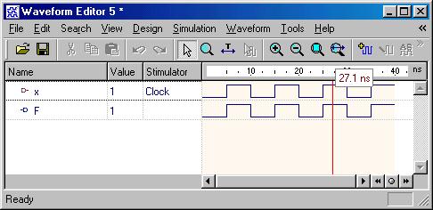
Besides from the circuit input and output signals, there are normally two other important signals, reset and clock, in the sequential circuit. The reset signal is either active-high or active-low status and the circuit status transition can occur at either clock rising-edge or falling-edge. Flip-Flop is a basic component of the sequential circuits.
| | | | | | |
| | | | | | |
| | | | | | |
Typical Combinational Components
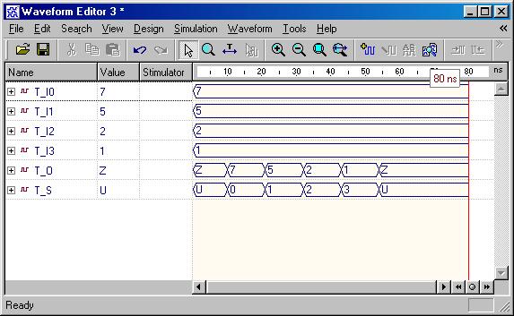
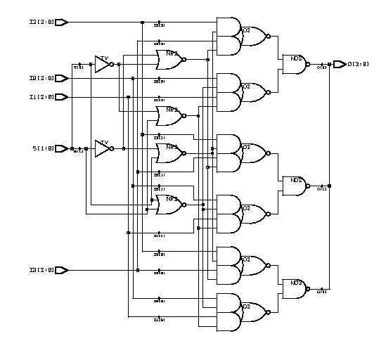
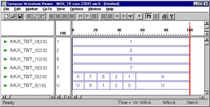
Typical Combinational Components
The following behavior style codes demonstrate the concurrent and sequential capabilities of VHDL. The concurrent statements are written within the body of an architecture. They include concurrent signal assignment, concurrent process and component instantiations (port map statement). Sequential statements are written within a process statement, function or procedure. Sequential statement include case statement, if-then-else statement and loop statement.
| | | | | | |
| | | | | | |
| | | | | | |
| | | | | | |
| | | | | | |
| | | | | | |
Basic Logic Gates
Basic Logic Gates
Every VHDL design description consists of at least one entity / architecture pair, or one entity with multiple architectures. The entity section of the HDL design is used to declare the I/O ports of the circuit, while the description code resides within architecture portion. Standardized design libraries are typically used and are included prior to the entity declaration. This is accomplished by including the code "library ieee;" and "use ieee.std_logic_1164.all;".
| | | | | | |
| | | | | | |
| | | | | | |
| | | | | | |
Subscribe to:
Comments (Atom)